In this tutorial, we will discuss how to use a thermal camera sensor in Ignition Gazebo.
There are currently a few limitations with the thermal camera, which will be mentioned at the end of the tutorial.
Requirements
Since this tutorial will show how to use a thermal camera sensor in Ignition Gazebo, you'll need to have Ignition Gazebo installed. We recommend installing all Ignition libraries, using version Citadel or newer (the thermal camera is not available in Ignition versions prior to Citadel). If you need to install Ignition, pick the version you'd like to use and then follow the installation instructions.
Setting up the thermal camera
Here's an example of how to attach a thermal camera sensor to a model in a SDF file:
Let's take a closer look at the portion of the code above that focuses on the thermal camera sensor:
As we can see, we define a sensor with the following SDF elements:
<camera>: The camera, which has the following child elements:<horizontal_fov>: The horizontal field of view, in radians.<image>: The image size, in pixels.<clip>: The near and far clip planes. Objects are only rendered if they're within these planes.
<always_on>: Whether the sensor will always be updated (indicated by1) or not (indicated by0). This is currently unused by Ignition Gazebo.<update_rate>: The sensor's update rate, in Hz.<visualize>: Whether the sensor should be visualized in the GUI (indicated bytrue) or not (indicated byfalse). This is currently unused by Ignition Gazebo.<topic>: The name of the topic where sensor data is published. This is needed for visualization.
Assigning a temperature to a model
Now that we have set up our thermal camera, we'll need to assign temperatures to models in the environment. If a model doesn't have a temperature associated with it, then the thermal camera cannot detect it.
Here's an example of a box model that has a temperature assigned to it:
Most of the code above is for the model - here's the key piece for temperature assignment:
Once the thermal system plugin is specified, all we need to do is include the <temperature> element, which specifies the model's temperature in Kelvin.
Running an example:
Now that we've discussed how a thermal camera and models with temperature can be specified, let's start an example world that uses the thermal camera.
Run the following command:
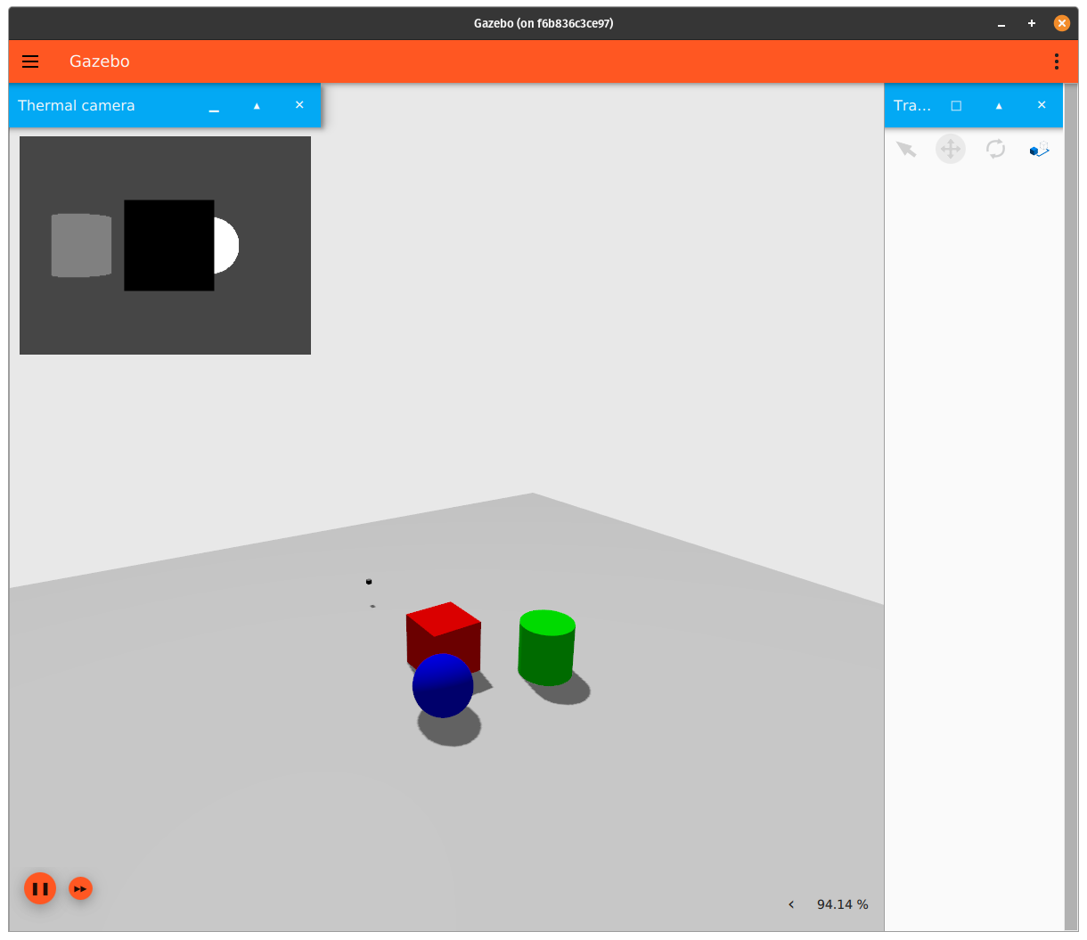
You should see something similar to this:
The window in the top-left corner shows the thermal camera's output. Taking a look at the SDF file for this example shows that the shapes were assigned the following temperatures:
- sphere: 600 Kelvin
- box: 200 Kelvin
- cylinder: 400 Kelvin
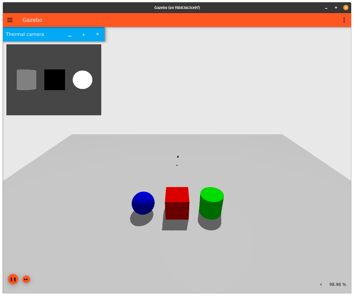
The temperature of objects in the view of the camera are normalized between 0 (black) and 255 (white) values. The object with the highest temperature in the camera's view will always have white color. If you move the object with the highest temperature out of the camera's view, the object with second highest temperature now becomes white.
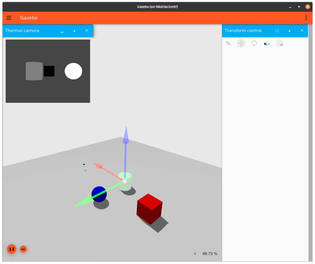
You can move the position of the shapes and/or camera around in the world to see the effect it has on the camera's output (the different "camera outputs" are how they are visualized in the GUI). An easy way to move objects in the world is by using Transform Control:
Processing the thermal camera's output
In the example above, the thermal camera publishes an image message to the /thermal_camera topic whenever the camera has a new image. We can observe the contents of a single message by running the following command:
Here are some important things to observe from the message output:
width: 320height: 240pixel_format_type: L_INT16 (16 bit integer)
This means that the image is stored in the message as a byte array of size 320x240 pixels. In order to do anything useful with the image stored in the message, we must convert the data in the array back to kelvin. Since the pixel_format_type is L_INT16, that means we need to cast the byte array to an array of unsigned 16 bit integers.
Here's an example thermal camera subscriber that performs this conversion:
Although most of the code above is described in the comments, let's go over the key points again:
- The image published by the camera is represented as serialized bytes. In order to read the actual temperature data that's stored in the image, we need to convert the data in the image to 16 bit integers.
- Once the image is stored in an array of 16 bit integers, we'll need to multiply the data in this array by the camera's linear resolution in order to ensure we are working with units of Kelvin. Since this thermal camera has a linear resolution of .01 (10mK), and the maximum value that can be stored in an unsigned 16 bit integer is 65535, this means that the maximum temperature that can be recorded by this camera is (65535 * .01) = 655.35 Kelvin / 680.72 F / 360.4 C.
Thermal Camera Limitations
The thermal camera has a few limitations:
- When assigning a temperature to a model, that temperature is applied equally across the whole model instead of having a gradient that falls off from the center of a heat source.
- The current implementation allows for a temperature to be assigned to a model, but doesn't allow for the location of a heat source in a model to be specified.
- If one object with a given temperature blocks another object with a given temperature (with respect to the thermal camera's point of view), the blocked object will not be displayed at all, regardless of each object's thickness and temperature difference between them (see the image below for an example). A more realistic implementation would have the camera display temperature fluctuations in the closer object if the temperature difference between the two objects is large enough, and if the closer object isn't too thick.
- More information about thermal camera behavior can be found here.
- There's a precision loss when the thermal camera converts temperature readings to grayscale output. To help quantify the magnitude of this precision loss, running the conversion code above on the example SDF file in this tutorial results in the following processed temperatures for each object in the camera's image:
- sphere: listed in the SDF file as 600 Kelvin, processed from the thermal camera image topic as 598.81 Kelvin
- box: listed in the SDF file as 200 Kelvin, processed from the thermal camera image topic as 200.46 Kelvin
- cylinder: listed in the SDF file as 400 Kelvin, processed from the thermal camera image topic as 400.92 Kelvin