Overview
This tutorial explains how to decide the frame of reference for your model and the conventions used in Gazebo.
Related tutorials
Gazebo world frame
This page captures some of the reference frames and conventions that we use in Gazebo. In general, Gazebo follows REP 103: Standard Units of Measure and Coordinate Conventions.
Gazebo's simulation is always performed in Cartesian coordinates (good old XYZ).

Additionally, Gazebo supports the use of real world latitude and longitude coordinates in its simulations using the WGS84 geodetic system. The world's Cartesian coordinates correspond to a local tangent plane at a given point on the planetary surface. By default, this plane follows the ENU (East-North-Up) convention, as shown on the image below:

Model frame
Gazebo follows the right-hand rule. The robot front facing surface is in the positive x direction, left facing being in the positive y direction, top facing being in the positive z direction and so forth.

Reference frame design considerations
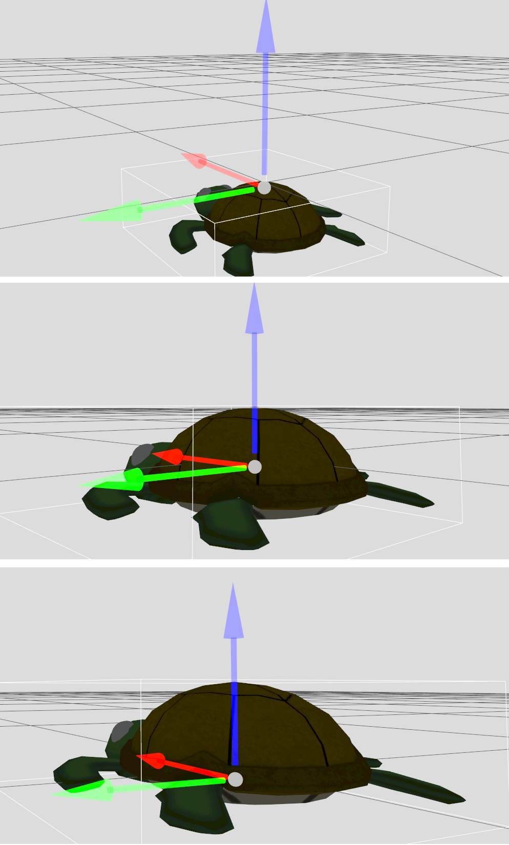
If you are creating a model, besides designing its kinematic structure (links and joints) and physical properties, you need to decide where to place your model's reference frame. Next are a few examples of our turtle model with three different choices for its reference frame.

Which one should I use then? There's no right answer here but here are a few recommendations:
- If your simulation model is based on a real-world model, try to use the same reference frame in simulation. This will simplify the process of creating and maintaining your model in simulation, as most of the measurements that you might find from your real-world robot will be transferable to your simulation model.
- Follow Gazebo's convention making
Xpointing forward,Ypointing left, andZpointing up. - Try to match the
Zvalue of your reference frame with the point of your model that contacts the ground or the water. That way, when you spawn your model at any point in the world, if you useZvalue of0, you know it will smoothly sit on a stable place.
How to set your model reference frame
There are a few ways to change the reference frame of your model:
- Adjust your mesh reference frame. When designing your mesh you'll be able to set its reference frame. It's recommended to match the mesh reference frame with the one you will want in Gazebo for your model.
- Add extra transformations via SDF. Your model SDF supports the ability to add transformations with the
<pose>tag to add extra offset to the visuals or collision elements of your model.
As a rule of thumb, try to minimize the number of transformations in your model to make it easier to reason about its reference frame.